Building HVAC systems are the core of indoor comfort and energy consumption control, covering heating, ventilation, air conditioning, and pipeline thermal insulation systems. In traditional HVAC acceptance, daily operation and maintenance, energy-saving renovation, and fault diagnosis, conventional methods such as pressure testing, manual inspection, point-by-point temperature measurement, and disassembly inspection generally have prominent drawbacks: low efficiency, destructive operation, high missing detection rate, and no visualized data support.
Infrared thermal imaging technology for HVAC inspection features non-contact, non-destructive, visualized, and full-area rapid scanning capabilities. It has become a mainstream solution for building HVAC acceptance, fault diagnosis, and energy efficiency testing. This technology accurately locates hidden problems including pipeline water leakage, insulation defects, building envelope heat loss, air system imbalance, and equipment overheating. Based on industry standards and on-site practical experience, this article presents a complete and implementable infrared thermal imaging inspection solution for full-scenario applications such as engineering acceptance, property operation, energy audit, and routine maintenance.
Core Application Scenarios & Practical Inspection Methods
Most HVAC faults are concealed inside building envelopes, hidden pipelines, and equipment, which cannot be identified by naked eyes or conventional tools. Infrared thermal imaging covers five key inspection modules: heating system, pipeline insulation, air duct system, building envelope, and HVAC equipment operation status.
1.1 Floor Heating & Radiator Pipe Leakage, Blockage, and Temperature Imbalance Inspection
Hidden pipeline leakage, air blockage, pipeline clogging, and uneven pipe spacing are the most common concealed faults in residential and commercial heating systems. Traditional pressure tests can only verify leakage existence but cannot pinpoint exact positions, often resulting in large-scale destructive renovation.
Practical Inspection Procedure:
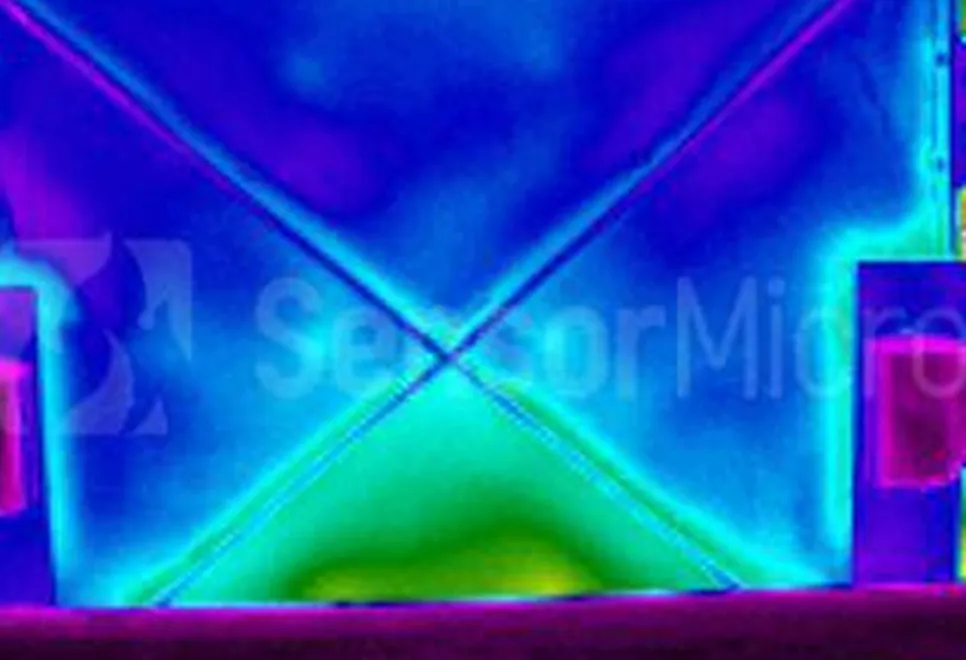
Run the heating system stably for more than 30 minutes to achieve complete thermal balance on floor and wall surfaces and ensure sufficient heat conduction. Scan heating areas evenly with an infrared camera. Normal pipelines present continuous, uniform strip-shaped thermal zones with consistent temperature distribution.
Fault Judgment Criteria: Local high-temperature spots or block thermal areas usually indicate pipeline leakage and hot water overflow; discontinuous temperature zones or obvious segment temperature differences represent pipe blockage, air lock, or irregular layout; partial low-temperature and sparse thermal areas reflect poor circulation and heating imbalance.
1.2 HVAC Pipeline Insulation Defects, Cold Bridge, and Heat Loss Detection
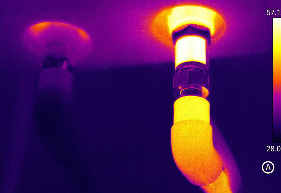
Damaged, fallen, thin, or poorly lapped insulation on central air conditioning pipes, heat pipelines, and water supply/return pipelines causes severe heat/cold loss, condensation, soaring energy consumption, wall mildew, and ceiling damp deformation.
Key Inspection Points: Scan full pipeline routes with emphasis on elbows, joints, valves, and supports during stable system operation. Well-insulated pipes show uniform and stable temperature. Defective insulation areas present obvious abnormal temperature: heating pipes show low-temperature anomalies while cooling pipes show high-temperature anomalies. Cold bridge positions and heat loss paths can be clearly identified for completion acceptance and energy-saving renovation inspection.
1.3 Air System Fault Detection: Uneven Air Supply, Air Leakage & Duct Damage
Damaged air ducts, joint air leakage, unbalanced air volume, and fresh air short circulation lead to poor indoor cooling/heating performance, high energy consumption, and uneven indoor temperature, which are frequent problems in office buildings, shopping malls, and commercial complexes.
Inspection Method: Operate air supply and return systems stably. Perform full scanning on air ducts, vents, ceiling concealed joints, and wall penetration points. Air leakage and duct damage form distinct temperature abnormal zones. Intuitive thermal image comparison helps locate short circulation, blockage, and leakage accurately to guide duct sealing and air volume balancing debugging.
1.4 Building Envelope Heat Loss Inspection: Walls, Windows & Roofs
Poor sealing of exterior walls, window gaps, roofs, and structural joints is the leading cause of high HVAC energy consumption and poor indoor thermal comfort, serving as a key item for building energy-saving acceptance. Referencing ASTM E3216-26 standard, standardized environmental conditions are required to ensure detection accuracy.
Standard Detection Conditions: Indoor-outdoor temperature difference ≥16.7℃; optimal inspection time is 2–3 hours after sunset to avoid direct solar radiation interference; ambient wind speed below 15km/h to reduce convection impact on temperature fields.
Fault Judgment: Thermal images clearly identify wall cavities, missing insulation, window gap air leakage, and roof cold bridges. Abnormal temperature zones mark exact heat loss positions, providing accurate data support for building sealing renovation and energy-saving upgrades.
1.5 HVAC Equipment Operational Fault Detection: Overheating of Chillers, Pumps & Fans
Long-term operation of chillers, air conditioning hosts, circulating pumps, and fans easily causes hidden risks such as bearing overheating, circuit overload, and local temperature rise. Traditional routine inspections fail to predict potential faults in advance, often leading to unexpected shutdowns and equipment damage.
Infrared thermal imaging realizes non-contact temperature measurement under live operating conditions, accurately locating overheating points and early risks of overload, jamming, and component aging. It supports predictive maintenance, reduces failure rates, and cuts long-term operation costs.


 CN
CN
 EN
EN